Man I miss Nekochan...
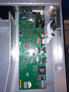
That small white power connector is the one I used to pull 48v for my X-Brick to V-Brick mod. I'm sure Nekochan had photos. It'll be a miracle if I can find the photos I took 13-14 years ago. They are probably somewhere on my NAS, but I've been insanely bad about organizing them.
After thinking about it while I fruitlessly searched the wayback machine...I have a strategy for you. First, see the docs
here, specifically the "
Switch, Connectors, and LEDs on R–brick Rear Panel" section. Get out your multimeter and put it into continuity mode. Put one probe on to the bare metal chassis and use the other probe on each of the three pins on the big black connector or small white connector. Both connectors should have one pin each connected to GND, 12V, and 48V. When you find continuity with the chassis, that's obviously your ground.
Next, the power switch on the back turns the L1 off/on. From the sounds of it, the L1 runs off of 12V from the power bay. Therefore, that switch must control the 12V line. Make sure the switch is on and pick either of the two wires connecting the switch to the power board. Put one probe there, and test the remaining two pins on the internal power connector. That'll be your 12V line.
The last line should be 48V.
When you have those three things figured out, you can start probing the connector on the back. Again, leave the power switch in the on position so you maintain continuity from the rear connector to the internal connectors. There should be several pins on the external connector that you don't care about because they carry data signals back to the power bay. What's left will be the GND, 12V, and 48V pins. As a sanity check, there should be quite a few more GND and 48V pins than 12V pins.