Octane PSU Repair - Click of Dead

megaimg

Member
Nov 24, 2021
32
18
8
Couple of weeks ago, I salvage an Octane, for my disappointment the PSU was behaving what everyone calls the click of dead. So, I post couple of messages on this forum and decided to take it on myself to try to fix it.... After fixing the SGI Fuel PSU (Sparkle Power Int Model FSP460-60PFN - Look at my other post), I was up for the challenge.

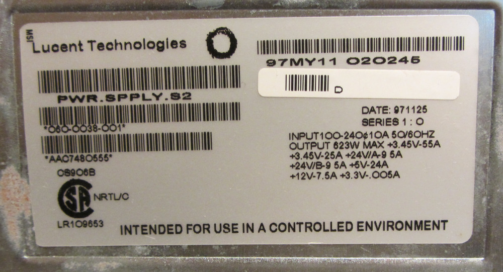
This is for The LUCENT TECHNOLOGIES 060-0028-003 623W

First, disassembly: (Sorry forgot to take pictures)
NOTE: You will be dealing with high voltage components, High Voltage Capacitors can hold charge, I cannot be responsible, do this at your own risk

The Unit is based on 3 different PCB units’ stock together on the metal enclosure. This is not rocket science. You keep track of the screws
Top PCB is hold by 4 screws. There is a cable that connect the top PCB with the middle one, easy to remove. The white external plug is easy to use a pair of needle pliers to push the connectors (don't unplug it from the PCB).

Disconnect the Power Cable input connector from the second board (Mark or label where the cables go, color base, easy) and remove it from the enclosure. Is hold by 2 screws. This will make easy the removal of the second PCB. Remove the connector that connect the secondary board to the third lower PCB and remove the board.

The last PCB is hold by 4 screws. Disconnect the Fan cable and is easy to feed it between the heatsink. You will have to push in another of the white external plug the same way you did on the first board, don't try to disconnect it from the PCB


Second - Recap:
List of Capacitor from Mouser.com
Mouser # QTY
75-517D476M025JA6AE36
710-8612214840086
667-EEU-FC0J682S6
647-UPV1H4R7MFD1TD1
647-UVK1E101MDD2
667-EEU-FM1V681B1
647-UPJ1V102MHD69
647-UPM1V222MHD1AA2
647-UBW1V221MPD1TD1
667-EEU-EB1J100S2
Replace All Capacitors in all 3 PCB. Note: theirs is one capacitor on the little AC/DC Control board in the secondary or middle PCB


Photo 1 - Bottom or third PCB board Recapped

Photo 2 - Middle or Second PCB board Recapped

Sorry, lost or forgot to take picture of the Top or first PCB board

After assembly and testing, no luck.... So removed this time the top board only, but left everything connected to the other boards of the PSU. I plug in the power, and I was able to verify that the click and bussing sound was coming from the secondary or middle PCB. Specific to one area.


So let start testing components. So I remove the AC/DC Control board and the complete top heatsink with all the MOSFET Transistors and components (You need to disorder all the components, this big heatsink has to be pull in one piece. After testing with a multimeter, found two parts that I was not happy with the results.
  • TOP292YAI - AC/DC Converters
  • 67F095 - Thermostats


So, decided to get replacement parts from Mouser:
  • For the 67F095 - Mouser Part# 874-67F095 (Same part still available)
  • For the TOP292YAI AC/DC Converter - Mouser Part# 869-TOP223YN (This has a little difference, the original is spec was 60W100/115/230 VAC, the new one is 50W100/115/230 VAC)

After Assembly, I can tell you that the Octane is Back online!
I had to do the LED MOD to the Light Bard!

Hope this help all you guys that are trying to keep this unit alive!
 
Last edited:
Thank you for detailing the fix! The dead power supply with click is such a common failure mode, I think this should be helpful to others, and it is great that the parts are still available :)
 
  • Like
Reactions: megaimg
Thank you for taking the time in documenting this, as Elf said it is extremely helpful!
 
  • Like
Reactions: megaimg
Super huge thanks for doing this. I have a Cherokee, but now if ever a Lucent comes up for cheap and it's not working, I'll take the chance and try and repair it! Glad to know it's actually possible (but I had little doubt it was...) :)
 
hi megaimg,

i've stumbled across this thread and read your repair advice with great interest, because i'm stuck with a similar problem. unlike your experience
with this typical "clicking" sound (restart attempts keep aborting due to some overload condition), my own faulty power supply (PS made by LUCENT)
is just dead silent; all 2-pin combinations from the two connectors (CON1 with 24 pins, CON2 with 14 pins) measure zero volts in standby mode, when
the PS is pulled out from the OCTANE. there should be some non-zero standby voltages available to at least feed the electronics around the OCTANE's
on/off button.

i followed your advice and replaced all the electrolytic caps on all boards, plus the power IC (TOP202YAI,- it was blown) and 2 faulty Z-diodes; the
thermostat (67F095) was OK in my case. afterwards nothing had changed, my PS remained in its dead state, exactly as it had been before.

next i inspected the circuitry in more detail and found that, unfortunately, the transformer associated with the blown power IC, yielding the standby
voltages, has gone south (open primary coil). i consider the chances of finding another suitable transformer as next to zero (unless recuperated from
some faulty PS of the same type), because it probably was uniquely produced for this special circuitry. and repairing of the bad transformer (rewind)
would be quite a hairy undertaking: e.g. the ferrite core, which is glued together, had to be removed, etc.

therefore, i intend to replace the entire standby section by a separate small PS. however, for this i'd have to know the standby voltages at the two
connectors CON1 and CON2. despite my extensive search efforts i was unable to find these infos (let alone the circuit diagram) on the web.

now i'd like to ask you or anyone with a good OCTANE PS if you could do me a big favor and measure the voltages in standy mode (it might also be
useful for other folks repairing such a PS). for this, first loosen the 2 screws and pull the PS out of the OCTANE. when the power cable is connected the
PS should be in standby mode (its fan should not spin up).

on the back side of the PS the 2 white power connectors CON1 with 24 pins (on the right side) and CON2 with 14 pins (on the top left side) can be
seen. i've numbered their pins in the following way:

CON1 consists of 2 vertical pin-columns with 12 pins each. in the left column the top pin is nr. 1 and the bottom pin is nr. 12; in the right column the
top pin is nr. 13 and the bottom pin is nr. 24. the numbering of CON2 is similar, with pin numbers ranging from 1 to 7 (left column) and from 8 to 14
(right column).

for CON1 the pins 6, 7, 8, 18, 19 and 20 are connected to MINUS/GROUND. i'd be interested to know the voltages (each measured w.r.t. ground) of the
following 6 pins: 1, 10, 12, 13, 22 and 24. in my opinion all the other pins should have 0V in standby mode.

for CON2 pins 3, 4, 6, 10, 11 and 13 are connected to MINUS/GROUND. the pins 2, 5, 9 and 12 are connected together; pin 7 is connected to pin 14.
i'd be interested to know the voltage of pin 8. all the other pins should measure 0V in standy mode,- if i'm not mistaken...

many thanks already in advance for your help and patience !
 
now i'd like to ask you or anyone with a good OCTANE PS if you could do me a big favor and measure the voltages in standy mode (it might also be
useful for other folks repairing such a PS). for this, first loosen the 2 screws and pull the PS out of the OCTANE. when the power cable is connected the
PS should be in standby mode (its fan should not spin up).

on the back side of the PS the 2 white power connectors CON1 with 24 pins (on the right side) and CON2 with 14 pins (on the top left side) can be
seen. i've numbered their pins in the following way:

CON1 consists of 2 vertical pin-columns with 12 pins each. in the left column the top pin is nr. 1 and the bottom pin is nr. 12; in the right column the
top pin is nr. 13 and the bottom pin is nr. 24. the numbering of CON2 is similar, with pin numbers ranging from 1 to 7 (left column) and from 8 to 14
(right column).

for CON1 the pins 6, 7, 8, 18, 19 and 20 are connected to MINUS/GROUND. i'd be interested to know the voltages (each measured w.r.t. ground) of the
following 6 pins: 1, 10, 12, 13, 22 and 24. in my opinion all the other pins should have 0V in standby mode.

for CON2 pins 3, 4, 6, 10, 11 and 13 are connected to MINUS/GROUND. the pins 2, 5, 9 and 12 are connected together; pin 7 is connected to pin 14.
i'd be interested to know the voltage of pin 8. all the other pins should measure 0V in standy mode,- if i'm not mistaken...
I fetched the three Lucent PSUs I have from storage and will try to have a look on the one that (should) still work (maybe already this evening). It's from an Octane I have on permanent loan. The other two units are unfortunately dead, thouhg not with the same symptoms IIRC. It could still be interesting to know their voltage reads.
 
many thanks already in advance for your help and patience !

So, here you go: First an image of the label on the PSU:
lucent-octane-psu-label.jpg


...then the actual readings (done with a voltmeter as I don't have an oscilloscope):

Code:
## Lucent Octane PSU backside ##

| PIN | READING | READING | PIN | CON #2
| --- | ------- | ------- | --- |
|  1  | 68.8 mV | 3.367 V |  8  |
|  2  | 0.524 V | 0.523 V |  9  |
|  3  | GND     | GND     | 10  |
|  4  | GND     | GND     | 11  |
|  5  | 0.519 V | 0.521 V | 12  |
|  6  | GND     | GND     | 13  |
|  7  | 1.008 V | 1.009 V | 14  |


                                        | PIN | READING | READING | PIN | CON #1
                                        | --- | ------- | ------- | --- |
                                        |  1  | ~250 mV | ~246 mV | 13  |
                                        |  2  |  1.3 mV |   -0 V* | 14  |
                                        |  3  |   -0 V* |   -0 V* | 15  |
                                        |  4  |   -0 V* |   -0 V* | 16  |
                                        |  5  |   -0 V* |   -0 V* | 17  |
                                        |  6  | GND     | GND     | 18  |
                                        |  7  | GND     | GND     | 19  |
                                        |  8  | GND     | GND     | 20  |
                                        |  9  |   -0 V* |  0.93 V | 21  |
                                        | 10  |  4.99 V |  4.96 V | 22  |
                                        | 11  |   -0 V* |      ^v | 23  |
                                        | 12  | 3.312 V | 3.313 V | 24  |

****

*) slowly rising to -0 V, similar to measurement between two GND pins.
^v) jumps around constantly, no clear reading possible.
 
  • Like
Reactions: bitpak
So, here you go: First an image of the label on the PSU:
lucent-octane-psu-label.jpg


...then the actual readings (done with a voltmeter as I don't have an oscilloscope):

Code:
## Lucent Octane PSU backside ##

| PIN | READING | READING | PIN | CON #2
| --- | ------- | ------- | --- |
|  1  | 68.8 mV | 3.367 V |  8  |
|  2  | 0.524 V | 0.523 V |  9  |
|  3  | GND     | GND     | 10  |
|  4  | GND     | GND     | 11  |
|  5  | 0.519 V | 0.521 V | 12  |
|  6  | GND     | GND     | 13  |
|  7  | 1.008 V | 1.009 V | 14  |


                                        | PIN | READING | READING | PIN | CON #1
                                        | --- | ------- | ------- | --- |
                                        |  1  | ~250 mV | ~246 mV | 13  |
                                        |  2  |  1.3 mV |   -0 V* | 14  |
                                        |  3  |   -0 V* |   -0 V* | 15  |
                                        |  4  |   -0 V* |   -0 V* | 16  |
                                        |  5  |   -0 V* |   -0 V* | 17  |
                                        |  6  | GND     | GND     | 18  |
                                        |  7  | GND     | GND     | 19  |
                                        |  8  | GND     | GND     | 20  |
                                        |  9  |   -0 V* |  0.93 V | 21  |
                                        | 10  |  4.99 V |  4.96 V | 22  |
                                        | 11  |   -0 V* |      ^v | 23  |
                                        | 12  | 3.312 V | 3.313 V | 24  |

****

*) slowly rising to -0 V, similar to measurement between two GND pins.
^v) jumps around constantly, no clear reading possible.

- - -

hi johnnym,

many thanks for taking the time to measure all the pins of both connectors and not only the ones i've suggested !  these are very valuable infos 
(probably not only) for me; AFAIK you're the first one who posted this in a public forum. hopefully you could obtain some hints of why your own 
two PS are not working ...

it looks as if there're basically 2 standby voltages available which are standard:  3.3V and 5V. i think  some ATX-like SMPS for PCs usually provide 
just 5V for the standby supply. without having inspected the circuit in more detail i don't know the purpose of the unusal voltages like 0.25V, 0.5V 
or 1V. for pin 11 of CON1  i've found out that it's hooked up to the data line of a small 1-line EPROM of type DS2505 where a globally unique 64-bit 
id is stored.
 
now i've to see if it's really feasible to replace the whole standby section of this PS by some separate add-on PS ...
 
thanks again for your kind support & bye for now.
 
Just started a repair project on a Octane PSU (Type Cherokee) which failed to switch on without pre-warning. No click of death etc.: https://forums.irixnet.org/thread-4349.html - will post my progress there and attached some pictures of the Octane and the opened supply.
 

Attachments

  • IMG_20240711_200229_616.jpg
    IMG_20240711_200229_616.jpg
    209.4 KB · Views: 7
  • IMG_20240711_200236_474.jpg
    IMG_20240711_200236_474.jpg
    414.2 KB · Views: 11
  • P7170024.JPG
    P7170024.JPG
    407.8 KB · Views: 14
  • P7170039.JPG
    P7170039.JPG
    496.7 KB · Views: 13
  • P7170044.JPG
    P7170044.JPG
    443.1 KB · Views: 14
Just started a repair project on a Octane PSU (Type Cherokee) which failed to switch on without pre-warning. No click of death etc.: https://forums.irixnet.org/thread-4349.html - will post my progress there and attached some pictures of the Octane and the opened supply.
Added some results on the investigation to the thread there (with pictures of the PCBs) - although no real success yet. Does anyone have more information esp. on the signals between Octane and the Power Supply? Did you know there is a 1 kBit memory (DS2505) inside the power supply?
 
Somehow the individual switch mode supplies (3V3, 5V, 12V and 24V) within my Cherkoee are working as intended. Interesting question: Did anyone see the phenomenon that his Octane did not power up, but the problem was NOT the power supply?
 
There have been limited reports of Octane's shorting damaging the power supply. But normally we see this with charring on the connector that interfaces between the XBOW and the power supply. These are so rare that no one has actually provided a damaged octane for somebody to research. So we don't exactly know what part goes short. All in all I've only seen seen maybe three or four instances online posted where the Octane itself was damaging power supplies and damaged itself. But in all of these the damage have been so overwhelming that the connector either partially melted or was also blackened. You can find these if you Google octane power supply issues then the past about five years.

Obviously it wouldn't be too hard to check the main power rails on the system & graphics modules with the multimeter to just see if they weren't in literal short. But it's an incredibly rare phenomenon and no one has actually dug deeper into it.
 

About us

  • Silicon Graphics User Group (SGUG) is a community for users, developers, and admirers of Silicon Graphics (SGI) products. We aim to be a friendly hobbyist community for discussing all aspects of SGIs, including use, software development, the IRIX Operating System, and troubleshooting, as well as facilitating hardware exchange.

User Menu