Indigo 2 Impact PSU dead, diagnosis & advice

stormy

Active member
Jun 23, 2019
201
82
28
Hi people,

I'm attempting to diagnose a Zytec 22943507 Rev C for Impact Indigo 2 systems.

PSU details:
psu details.jpg

Description of fault:
Absolutely no output when power applied. Connecting 'run' pin 11 to 'standby 5v' pin 5 does not start the PSU. No output on pin 5 'standby 5v' at all.

Some things already done: Replaced most of the capacitors on both HV and LV sides, as suggested on Ian Maplesons guide. The only caps not replaced yet are the super-large two on the HV side and the 6800uf caps. I have also re-soldered most points on the boards that get hot, to make sure the solder is good. None of this helped.

In-depth testing:

I do not have an impact graphics terminator, it wasn't attached to my PSU like others, so I had to make one from scratch:
make graphics sense.jpg make graphics sense 2.jpg make graphics sense 3.jpg

I measured which side was GND and plugged the sense cable in for black to GND yellow to 3.5v.

Another thing I was interested in was the initial AC filter. I tested the continuity and it all seemed fine. I opened it up and took a picture just for the record:
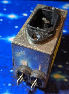
AC filter 1.jpg AC filter 2.jpg AC filter 3.jpg AC filter 4.jpg
 
Last edited:
  • Like
Reactions: Elf
I want to measure the connectors that go from HV > LV boards. So I plugged my load resistors in to pins 15 & 16 (5v & GND) on the left connector, then pins 13 & 15 (12v & GND) on the right connector. My 5v load resistor is 2R2K and my 12v is 10R. I also connected a hard disk to the Molex for extra load & connected my home made graphics cable terminator.

These are the measure points, I put arrows on the PCB where the connector points are:
measure points.jpg

Here is a photo of the HV side:
HV side.jpg
Here is a photo of the LV side:
LC side.jpg

Photos of my load setup:
load setup 1.jpg load setup 2.jpg

Photo of the PCB dismantled for taking the measurements:
measure points 2.jpg
Of course I have checked the fuses, and just for the record here are some resistors on the HV side that get hot (and show by the PCB discoloration:
Fuses.jpg Hot resistors 1.jpg Hot resistors 2.jpg

Result of testing so far:

Absolutely nothing on the output of the HV>LV connectors. But I did notice those resistors are getting hot on the HV side still.
 
  • Like
Reactions: Elf
Any suggestions on my next steps appreciated. I assume the problem must be on the HV side after these tests? Thanks.
ps - Cheers for all your details about these psu's on the forum @Elf
 
I am thinking it may be worth replacing the AVS1AC (datasheet attached)
There are also 2x MOC 8101 optocouplers I am thinking of replacing (datasheet attached)

Thoughts?
 

Attachments

  • avs10cb.pdf
    330.4 KB · Views: 264
  • moc8101.pdf
    157.5 KB · Views: 276
Edit: With apologies, I no longer wish to have involvement with SGUG or SGI communities in general,
and have also chosen to remove all of my content. Many things have changed since I co-founded, named, and ultimately
then left SGUG. There are many good people around, to whom I apologize for frustrating by removing these things, and
also many petty people that over the years whittled down both the enjoyment as well as sense of obligation I used to
feel to anyone else regarding what was ultimately just a hobby. Unfortunately one of the latter now writes the rules
and so it is time for me to take my things and go.

This message will replace all of my previous forum posts because deleting threads that I started would have removed
other peoples' posts.
 
Last edited:
Well, I have a thermal imager, so I cheat. Normally I used a 300W current limiting light bulb setup for draw indication. Usually you either have a non-starting, constantly restarting (pulsing bulb), or a start followed by a protection mechanism engaging.

I use a thermal imager to stare (briefly) at the PSU PCBs while powered, shows shorted Diodes and FETs very well. If it's a resistor issue, that's very different. If you want to troubleshoot a resistor issue, desolder one-end of each resistor and recheck its value against markings, replace if out of spec.

I do not normally testing PSUs powered (I have a lot of power-off testing gear), but assuming you have a current limiting setup made from a light bulb with enough wattage to allow normal startup, it's great way of doing a cheap voltage injection-style hunting.
 
  • Like
Reactions: ruckusman and Elf
Update, I am getting 7.7v AC and 5v AC from the double thick wires going from HV to LV.
 
@mc68k Might as well update this thread after so long: Yes it works now, I stupidly ended up re-capping the entire thing (which made no difference) I then gave it to my friend. He literally just re-flowed the solder around any hot components, like transistors or things connected to heatsinks, it then sprang to life.

So TLDR; if you have trouble with these PSU's, try reflowing any components that get hot. Cracked solder joints are a very likely issue.
 
  • Like
Reactions: ruckusman
That makes sense. I've been working on some old CRTs as a recently and cracked solder joints are a huge issue. The most notable way to see if that's the case with those is to use the Fonzie method on them
 
  • Like
Reactions: ruckusman

About us

  • Silicon Graphics User Group (SGUG) is a community for users, developers, and admirers of Silicon Graphics (SGI) products. We aim to be a friendly hobbyist community for discussing all aspects of SGIs, including use, software development, the IRIX Operating System, and troubleshooting, as well as facilitating hardware exchange.

User Menu