DISCLAIMER: Opening a power supply and performing repairs to it could be deadly! Do not attempt any repairs if you do not know what you are doing.
Hello all,
Thought I should write something about my most recent repair project here. Currently I have one almost dead Indigo2 Impact PSU (060-8002-001 Rev A) on-going repairs.
At the first round, I decided to try to follow a guide pointed out to me by Ian (http://www.sgidepot.co.uk/i2psu.html). I managed to successfully replace the mentioned capacitors on the High Voltage side of the supply, but that did not help. So now this week, I have started to finally investigate the Low Voltage side of the supply. This is probably the most difficult PSU I have attempted to repair so far. As Elf's great reverse engineering post indicates, the LV and HV sides are soldered into each other with thick slices of copper and it makes it difficult to work with.
So, for the Low Voltage side. I found one SOT-23 packaged component that looked suspicious when I did optical inspection of the LV board.
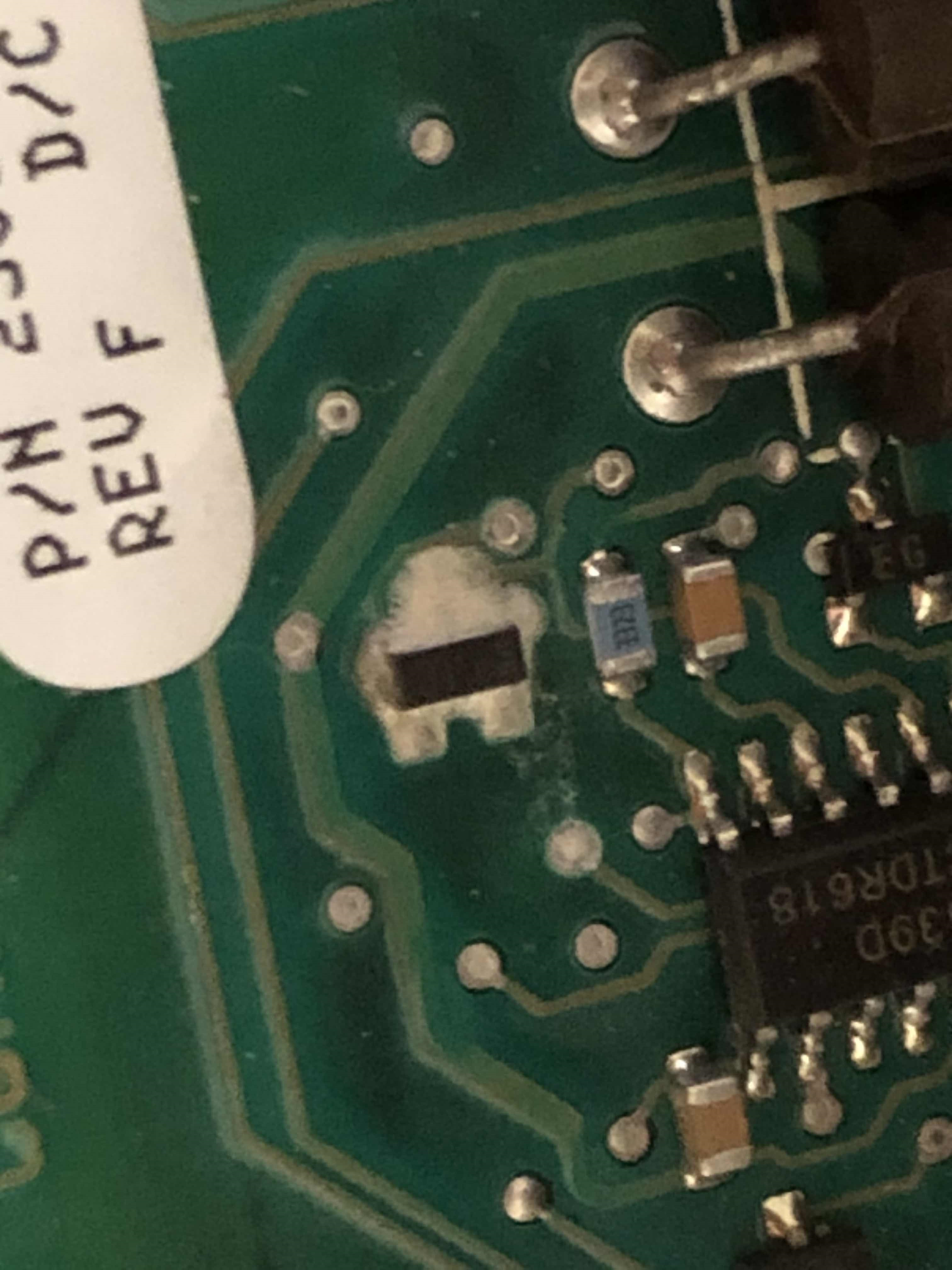
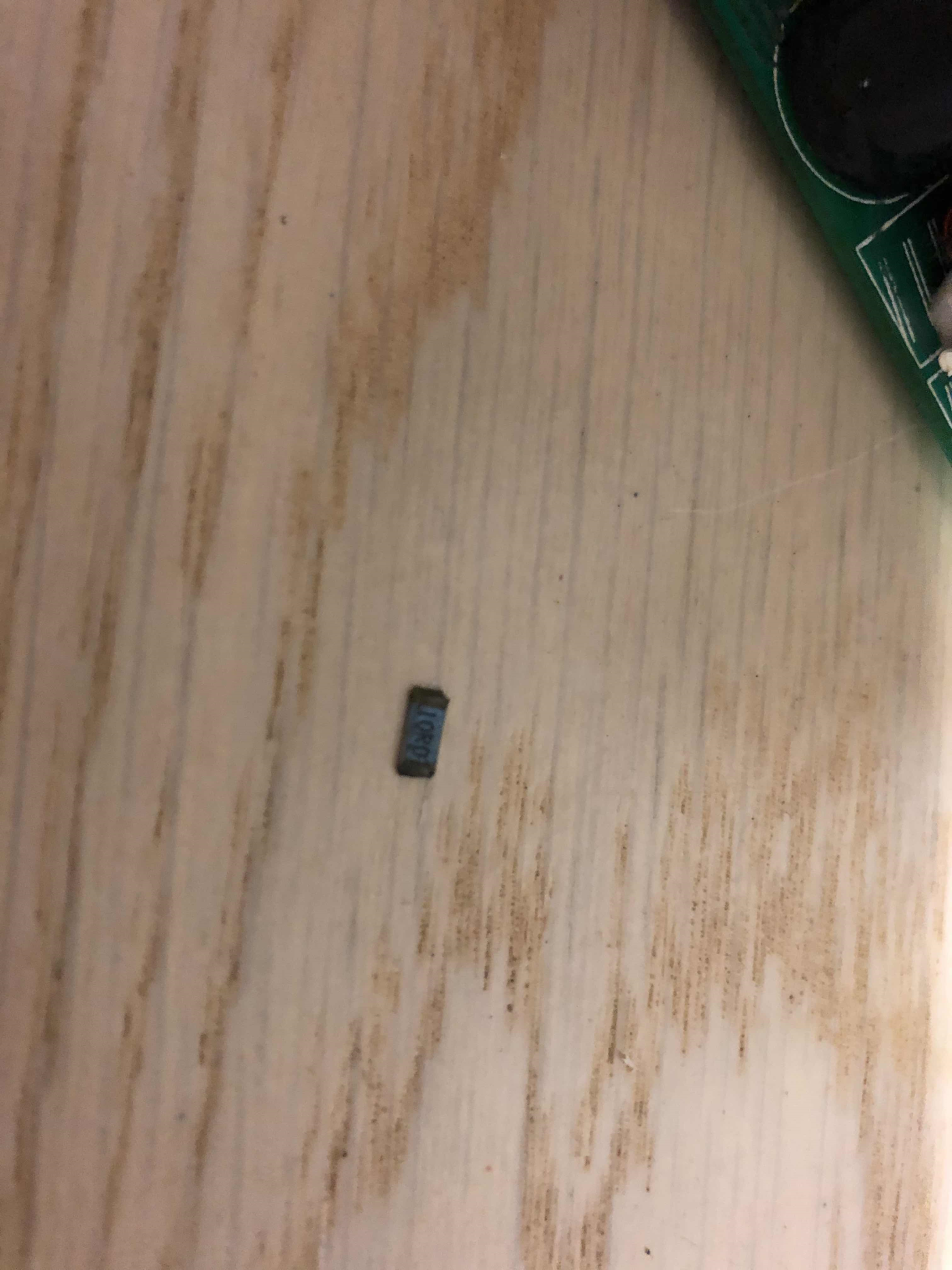
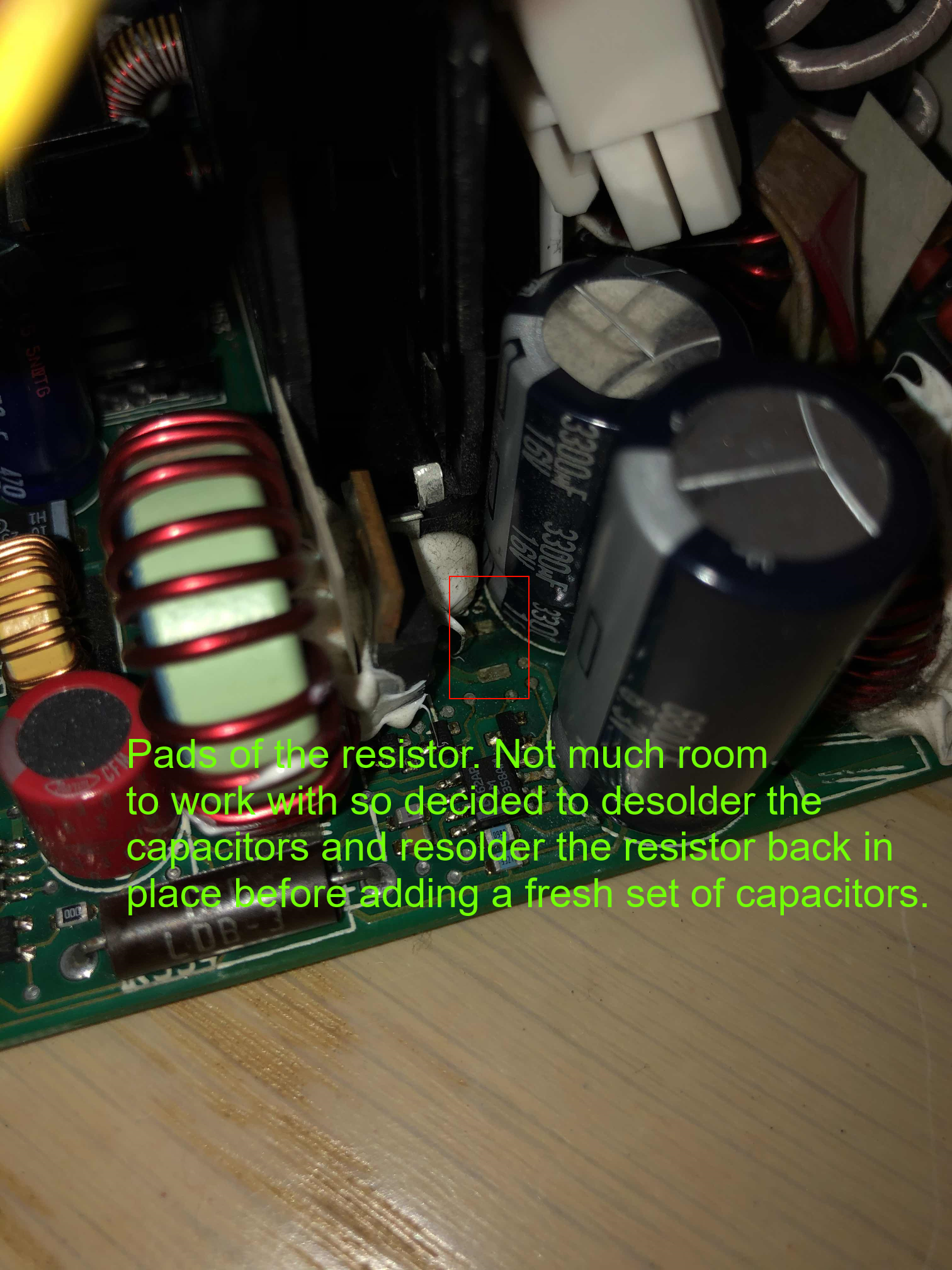
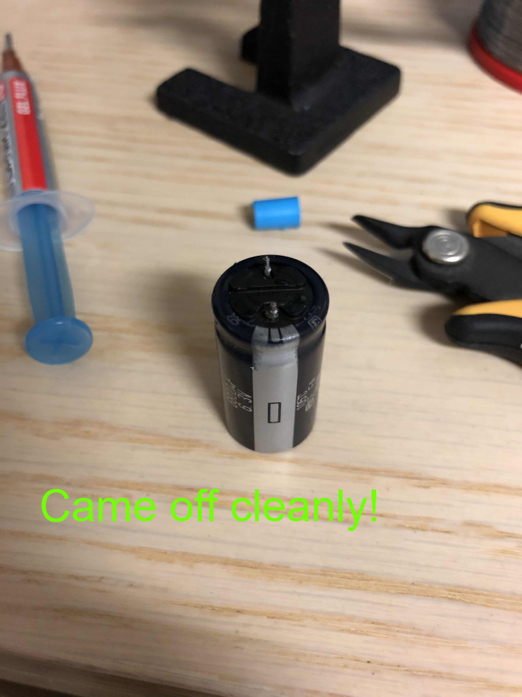
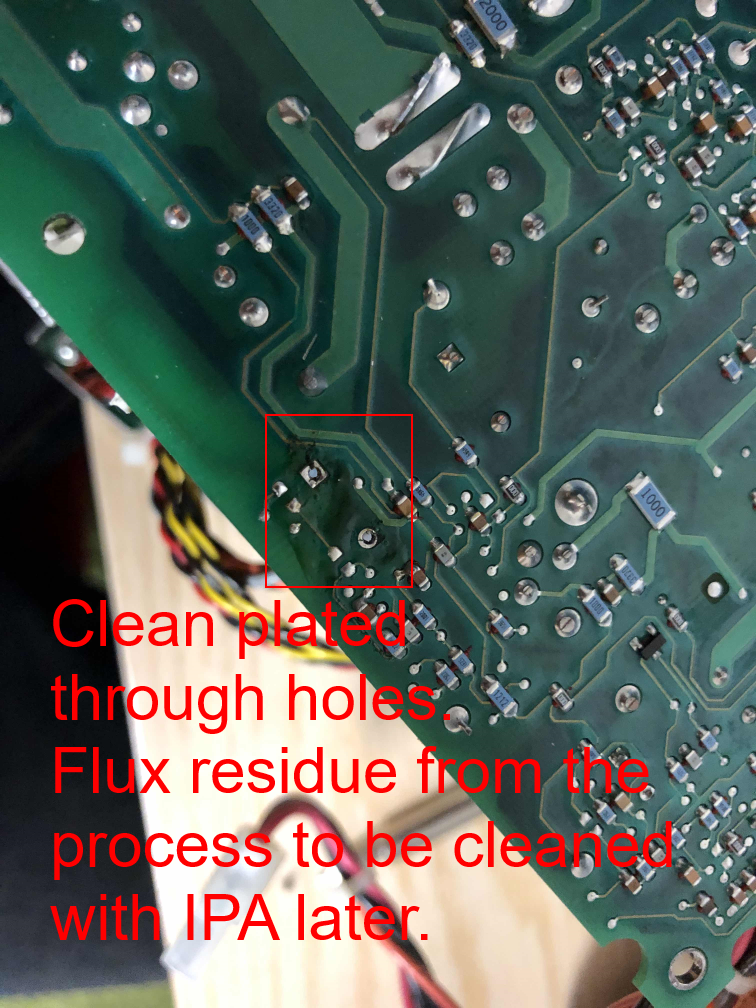
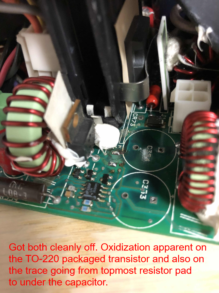
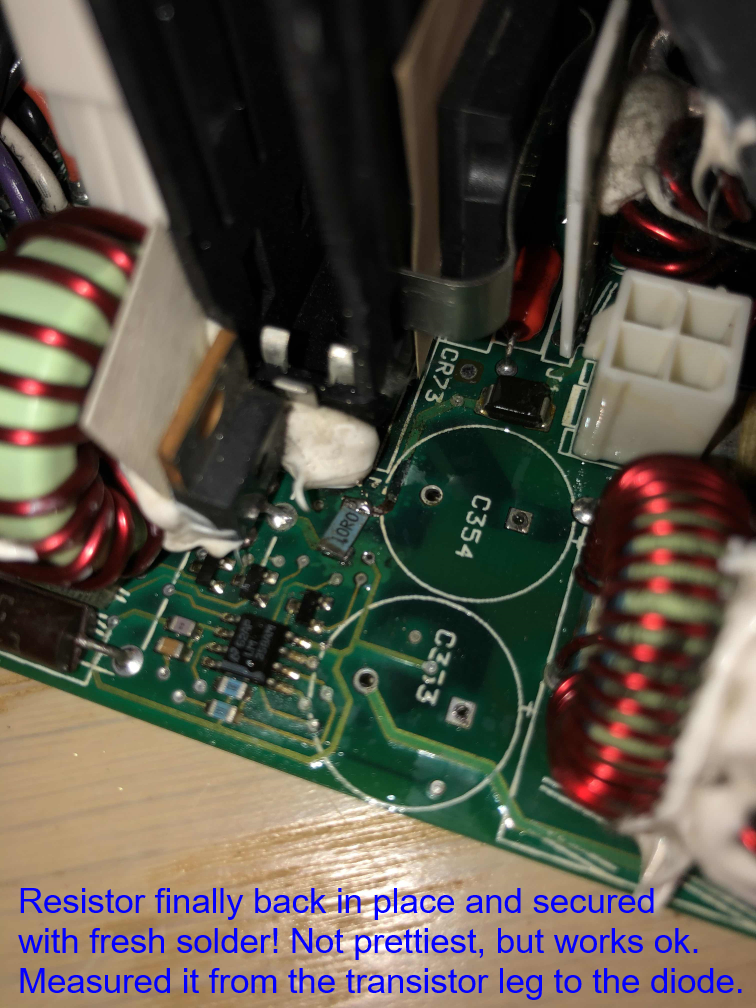
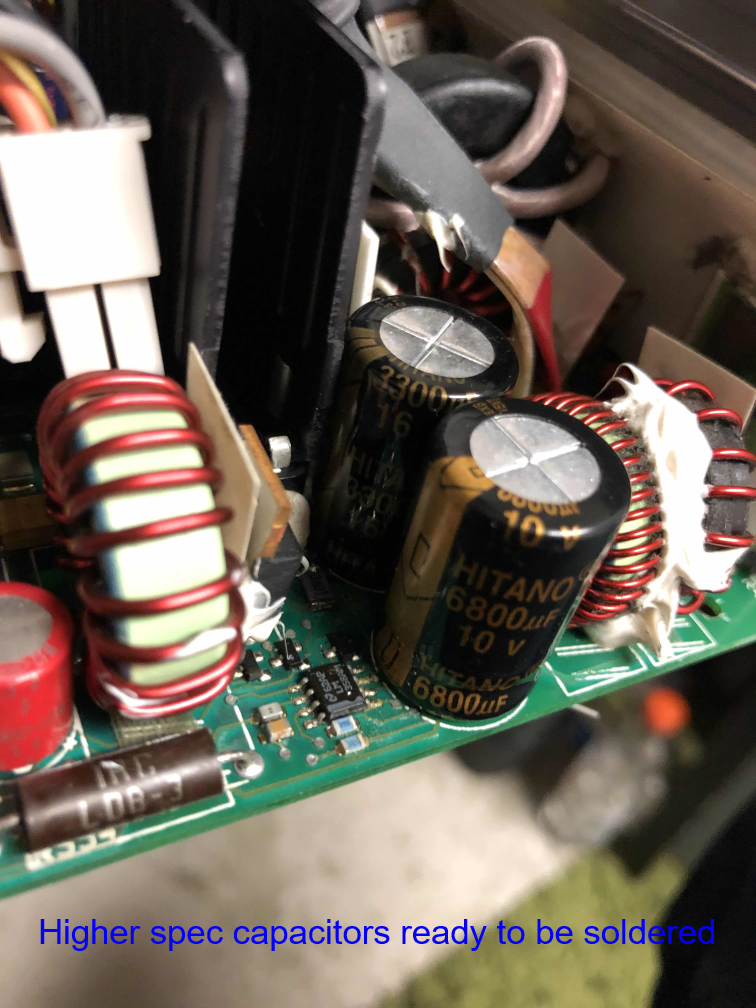
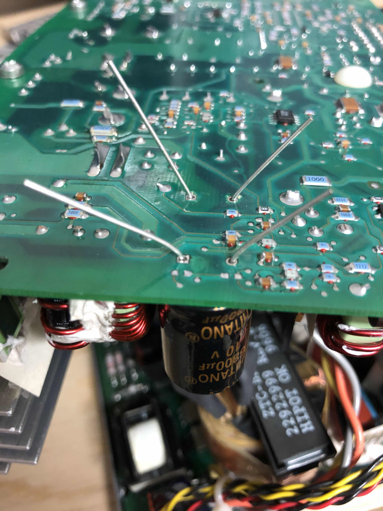
Also, on the opposite side of the board were some signs of dust and solder seemed to have blackened on a resistor. When cleaning that section with gas duster, the said resistor learned to fly, so to make space to put it back I replaced the closest capacitors to it. Also, as the contacts on the board and on the component were blackened, I used a scalpel to carefully scrape off the oxidized layer and applied some fresh solder on them. Here is a series of pictures of that process:
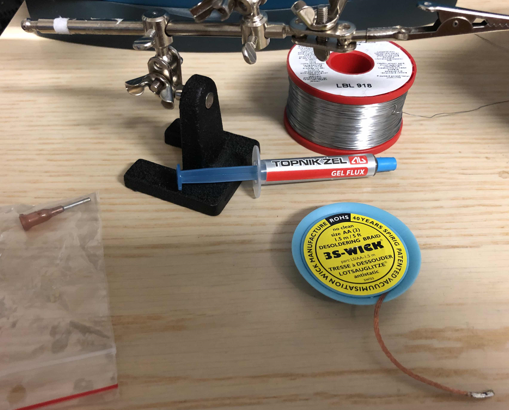
To remove the capacitors, I used a soldering iron with chisel tip and 350 Celsius degrees set as temperature along with gel flux, leaded solder, and most importantly, a solder wick.
To be continued on next post!
Hello all,
Thought I should write something about my most recent repair project here. Currently I have one almost dead Indigo2 Impact PSU (060-8002-001 Rev A) on-going repairs.
At the first round, I decided to try to follow a guide pointed out to me by Ian (http://www.sgidepot.co.uk/i2psu.html). I managed to successfully replace the mentioned capacitors on the High Voltage side of the supply, but that did not help. So now this week, I have started to finally investigate the Low Voltage side of the supply. This is probably the most difficult PSU I have attempted to repair so far. As Elf's great reverse engineering post indicates, the LV and HV sides are soldered into each other with thick slices of copper and it makes it difficult to work with.
So, for the Low Voltage side. I found one SOT-23 packaged component that looked suspicious when I did optical inspection of the LV board.
Also, on the opposite side of the board were some signs of dust and solder seemed to have blackened on a resistor. When cleaning that section with gas duster, the said resistor learned to fly, so to make space to put it back I replaced the closest capacitors to it. Also, as the contacts on the board and on the component were blackened, I used a scalpel to carefully scrape off the oxidized layer and applied some fresh solder on them. Here is a series of pictures of that process:
To remove the capacitors, I used a soldering iron with chisel tip and 350 Celsius degrees set as temperature along with gel flux, leaded solder, and most importantly, a solder wick.
To be continued on next post!
Last edited:
