It's time for more Power Supply Basics! This time of the Silicon Graphics / SGI O2. This one had less to figure out than the Indigo 2 and Indy.
If referencing or duplicating this information, I ask that you maintain a prominent link to this original forum post for further updates, as well as a credit by name.
At least of the time of this writing, you won't get any better power supply information than at the Silicon Graphics User Group!
Here is the power supply pinout from the O2 front plane perspective, looking from the back into the recessed cubby hole for the PSU:
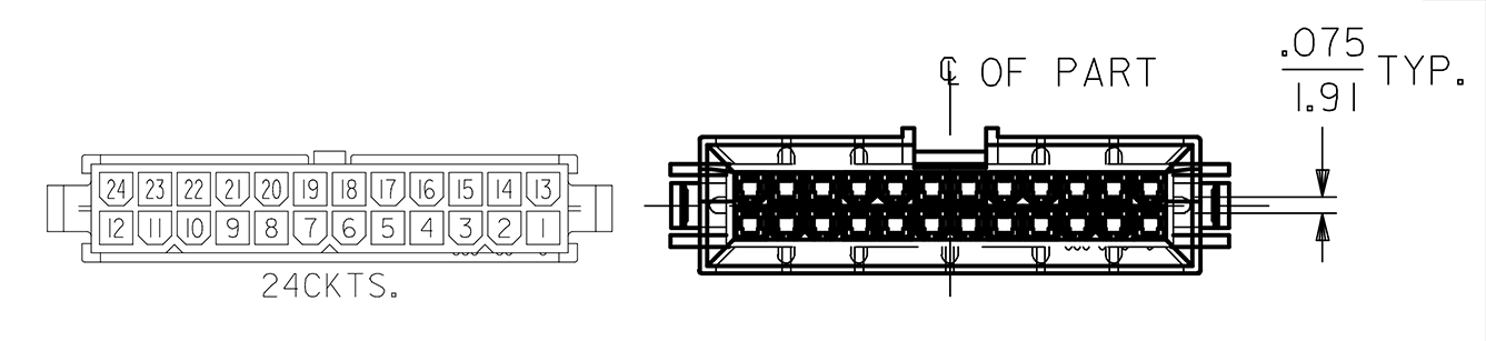 Power is supplied over a 24 pin Molex Mini-Fit BMI connector. This is like the Mini-Fit Jr. commonly found on wire to board solutions, but has guide posts and no clip. A 24 pin Mini-Fit BMI "plug" (machine side) is pictured to the right, with the Mini-Fit Jr. to the left for pin number reference purposes.
The O2 front plane (which connects the motherboard, power supply, and other accessories) has the male pinned connector, while the O2 power supply has the female connector.
+3.3V standby (Aux) power is supplied when the PSU is connected to AC Line power, but has not yet been turned on. In contrast to the Indy and Indigo 2 PSUs, the O2 PSU does not turn itself on by default, and the Run line must be grounded to start.
Pin numbers are as per the mechanical drawing. Wire colors are internal to the power supply, as only the connector is exposed when fully assembled.
The unit under test is Sony model APS-90 / part # 8-68-1189-41, SGI part # 060-0022-001, with the following specifications:
Unlike the Indy and Indigo 2 which have most of their capacity on the +5V rail, the O2 is primarily +3.3V driven, with more of its power on the oddly spec'd +3.43V rail. The 3.43V regulation was confirmed. Standby power comes from a separate converter, and is at 3.3V, versus the main power rail.
Power factors were in the 0.6 area; bad as usual! Standby power is about 4 Watts. No precise numbers this time around, although they could be reported if desired.


As you can see the O2 PSU underwent the usual test setup. Initially what gave me some trouble was the nature of the two sense lines. Without Pin 1 (red / small) and Pin 13 (grey / small) connected to the +3.43V rail and 0V return respectively, the power supply goes wildly out of regulation. The +3.43V rail will swing above 5V, and the power supply has a tendency to shut down under any load.
This made it difficult to test until I uncovered the nature of the sense lines by testing the O2 front plane. I am still uncertain why there is a feedback connection for the 0V return, but without this second sense line connected the PSU does not operate properly.
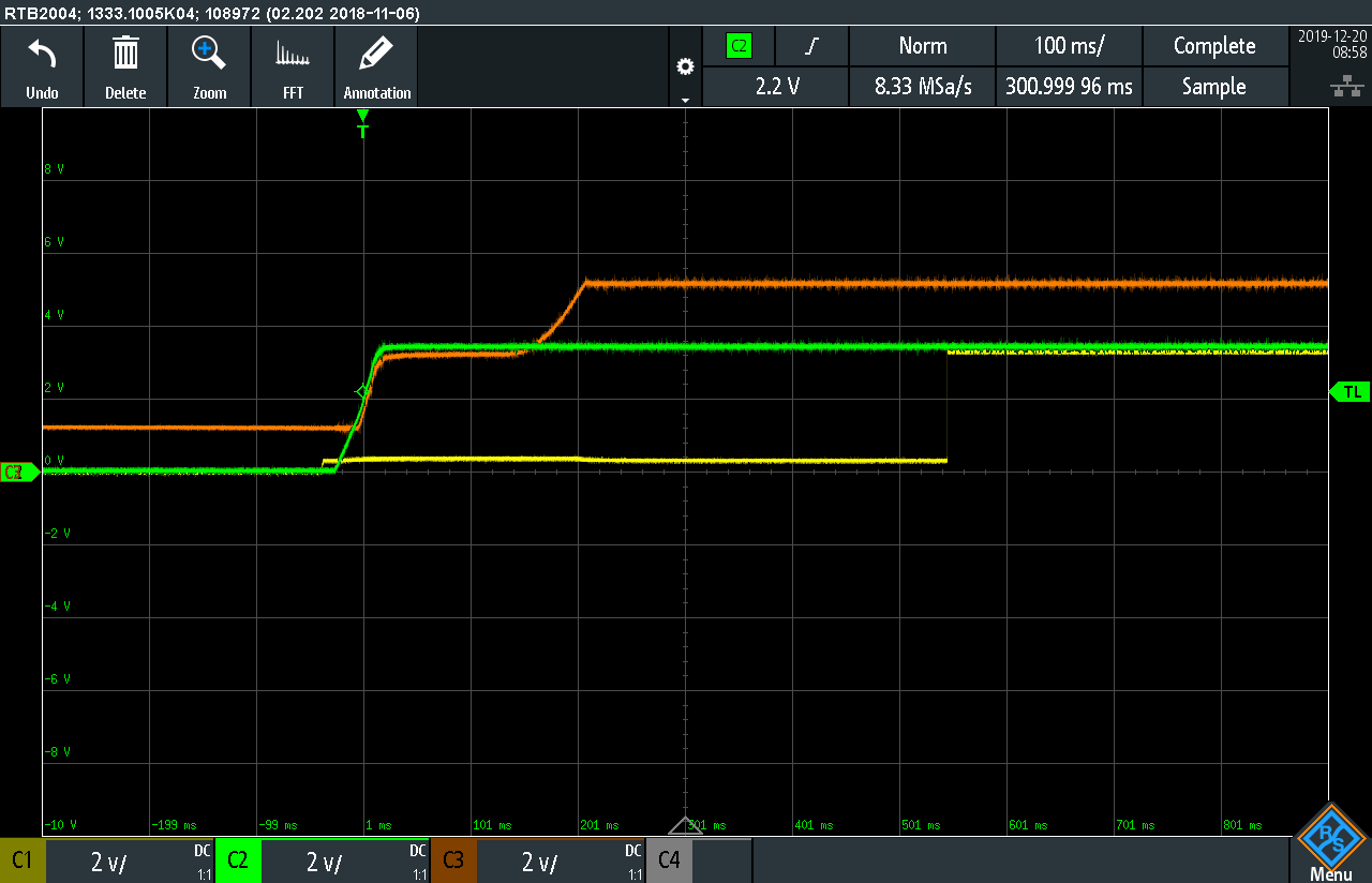
(C1 - Pgood, C2 - +3.43V, C3 - +5.1V)
Pin 14 (power good) is asserted at a 3.3V logic level well after the +3.43V and +5.1V rails have stabilized. Notice the odd ramp up of the +5.1V rail, closely following the +3.43V rail until it gets a bit more of a boost about 150ms after +3.43V has stabilized. Strange! Examining the conversion stages would probably make more sense of this.
If referencing or duplicating this information, I ask that you maintain a prominent link to this original forum post for further updates, as well as a credit by name.
At least of the time of this writing, you won't get any better power supply information than at the Silicon Graphics User Group!
Here is the power supply pinout from the O2 front plane perspective, looking from the back into the recessed cubby hole for the PSU:
The O2 front plane (which connects the motherboard, power supply, and other accessories) has the male pinned connector, while the O2 power supply has the female connector.
+3.3V standby (Aux) power is supplied when the PSU is connected to AC Line power, but has not yet been turned on. In contrast to the Indy and Indigo 2 PSUs, the O2 PSU does not turn itself on by default, and the Run line must be grounded to start.
| Pin # | Wire Color / Size | Function |
|---|---|---|
| 1 | Red / small | +3.43V rail feedback / sense |
| 2 | Blue / small | Run (Ground to start) |
| 3 | Red / large | +5.1V |
| 4 | Red / large | +5.1V |
| 5 | Black / large | 0V |
| 6 | Black / large | 0V |
| 7 | Black / large | 0V |
| 8 | Black / large | 0V |
| 9 | Black / large | 0V |
| 10 | Yellow / large | +3.43V |
| 11 | Yellow / large | +3.43V |
| 12 | Yellow / large | +3.43V |
| 13 | Grey / small | 0V return feedback / sense (?) |
| 14 | Brown / small | Power good signal (3.3V) |
| 15 | Yellow / small | +3.3V Standby |
| 16 | Purple / small | +12V |
| 17 | Orange / small | -12V |
| 18 | Black / large | 0V |
| 19 | Black / large | 0V |
| 20 | Black / large | 0V |
| 21 | Black / large | 0V |
| 22 | Yellow / large | +3.43V |
| 23 | Yellow / large | +3.43V |
| 24 | Yellow / large | +3.43V |
The unit under test is Sony model APS-90 / part # 8-68-1189-41, SGI part # 060-0022-001, with the following specifications:
| Rail | Rating |
|---|---|
| +3.43V | 31A |
| +5.1V | 10A |
| +12V | 3.2A |
| -12V | 0.25A |
| +3.3V Standby (Aux) | 10mA |
Unlike the Indy and Indigo 2 which have most of their capacity on the +5V rail, the O2 is primarily +3.3V driven, with more of its power on the oddly spec'd +3.43V rail. The 3.43V regulation was confirmed. Standby power comes from a separate converter, and is at 3.3V, versus the main power rail.
Power factors were in the 0.6 area; bad as usual! Standby power is about 4 Watts. No precise numbers this time around, although they could be reported if desired.
As you can see the O2 PSU underwent the usual test setup. Initially what gave me some trouble was the nature of the two sense lines. Without Pin 1 (red / small) and Pin 13 (grey / small) connected to the +3.43V rail and 0V return respectively, the power supply goes wildly out of regulation. The +3.43V rail will swing above 5V, and the power supply has a tendency to shut down under any load.
This made it difficult to test until I uncovered the nature of the sense lines by testing the O2 front plane. I am still uncertain why there is a feedback connection for the 0V return, but without this second sense line connected the PSU does not operate properly.
(C1 - Pgood, C2 - +3.43V, C3 - +5.1V)
Pin 14 (power good) is asserted at a 3.3V logic level well after the +3.43V and +5.1V rails have stabilized. Notice the odd ramp up of the +5.1V rail, closely following the +3.43V rail until it gets a bit more of a boost about 150ms after +3.43V has stabilized. Strange! Examining the conversion stages would probably make more sense of this.
Last edited:
