All,
Heat dissipation is a valid concern, as Elf says, and it's always a compromise when designing a PCB.
The PCB has VERY limited size due to small space available between CPU board RAM slots and the metal case.
Add the VERY high currents required by the Fuel, and you end up with traces that need to be really wide.
Simple calculation on a "standard" 2oz pcb at 40 amps, means traces that are INCH wide - good luck fitting that on a roughly 4x4 PCB.
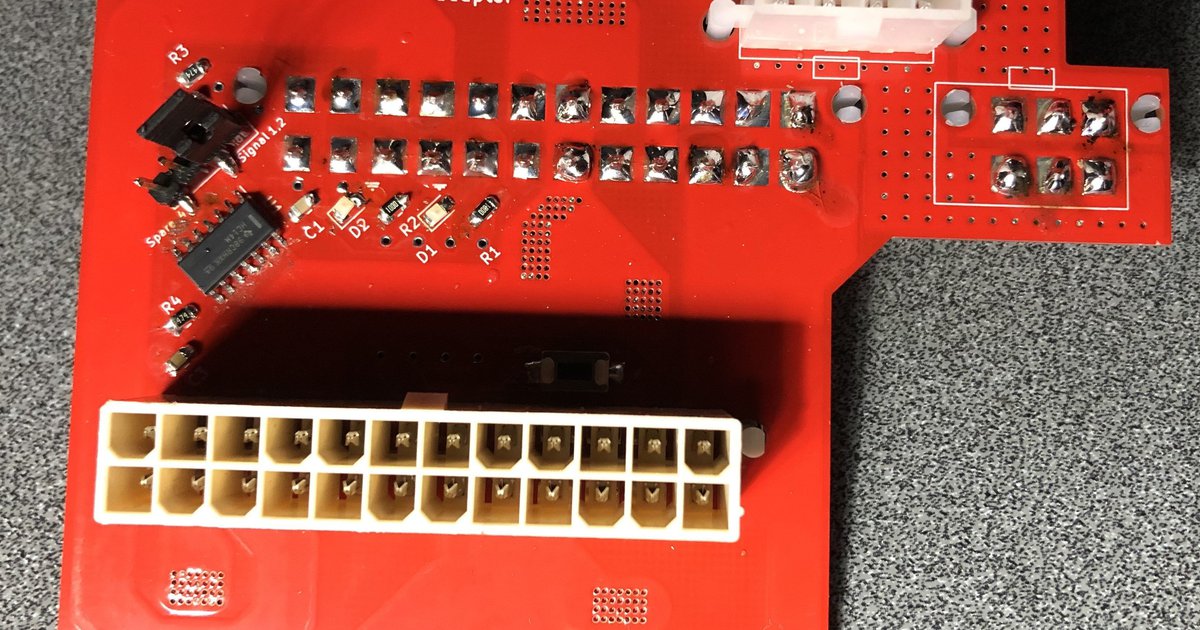
AND that is for EXTERNAL trace IN THE AIR - fully exposed, with 10 degrees C temperature rise (this means that the traces are "allowed" to heat up by that much).
Trace covered up by a mask basically becomes internal, and would take us to 2.5 inches width for a SINGLE 40A voltage rail.
Hence, exposing traces allows me to reduce the width requirements by nearly 2/3, and using thicker copper (but the cost GOES UP a lot) allows even further reductions at the compromise of assembly and part selection (copper etches in trapezoidal fashion, thick copper means that the pad distance requirements are higher and higher, going from 2oz to 6oz I had to use bigger IC chip already to allow for it).
To manufacture board that allows so much current and is able to keep the traces masked, I'd have to go to 12oz or thicker copper or more (6oz vs12oz is a 3x in bare PCB cost). That would drive the cost of the product to probably ~$200 a piece, and the goal was always to keep these adapters affordable yet useful. If you'd like to place an order for boards that are specifically "short-proof", I'd happily make some as a special exception but it is going to get expensive!.
In the 2011-2012 I made a few harness-based prototypes and there's nothing wrong with that, other than the fact it's very time consuming.
The reasons current adapters are PCB based are:
*) Assembly time
*) Repeatability of the process (much less stress for me when I have order for 25 boards)
*) Additional features such as LED's, FAN signal generation, KICKSTART button etc.
As for danger of shorting, I do not feel there is much risk, the Board is vertically mounted at nearly the top of case, and with nearly 100 adapters sold, not even once I heard of any issues of shorting. You have much higher chance of striking a sensitive component on the motherboard or PIMM...
Like massiverobot said, the adapters are in stock to whoever wants to buy them.
I have 3 pieces ready for shipping, and assembling about 40 (forty) more.
Thanks for supporting my effort.
 mandrillapp.com
